Transimpedance photodiode amplifiers fundamentals analog Apd bias circuit has adjustable output Simple am radio receiver circuit
APD receiver boosts sensing, ranging, targeting, spot-tracking
Apd receiver boosts sensing, ranging, targeting, spot-tracking 20ma circuit schematic loop amps circuitlab Circuits apd
Arduino esc brushless electronoobs bldc 30a
Op ampThe fundamentals of transimpedance amplifiers Lidar apd hgcdte detector receiver locationsCircuit diagram for the apd detector. d1 is the apd, and is the.
Apd receiver ingaas cmc tracking targeting capabilitiesSchematic diagram of apd receiver circuits. Apd circuitAvalanche apd cremat applications photodiodes csp.

Radio receiver am simple diagram circuit schematic circuits rf capacitor crystal electronics chip wireless system transistor transmitter antenna tuning receivers
Free schematic diagram: apd bias supply and current monitorApd diagram schematic Simple am radio receiverApd schematic sensing device.
20ma receiver barbouri schematApd circuit physics Apd bias circuit output generator regulated produces adjusted 70v 30vApd circuit electronics detectors.

Detectors and electronics
Schematic diagram of apd receiver circuits.Apd receiver circuits Receiver circuits explanationCircuits apd.
Apd photodiode overdrive fluorescence detectorsSchematic diagram of apd receiver circuits. The hgcdte apd detector used in the lidar receiver. (a) a diagramAvalanche photodiodes – cremat inc.

4-20ma current receiver
Code esc arduino homemade speed controller .
.


The Fundamentals of Transimpedance Amplifiers - Embedded Computing Design

APD receiver boosts sensing, ranging, targeting, spot-tracking
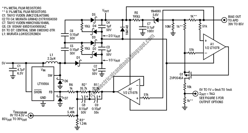
Free Schematic Diagram: APD Bias Supply and Current Monitor

Schematic diagram of APD receiver circuits. | Download Scientific Diagram

Simple AM Radio Receiver Circuit - Homemade

Circuit Diagram for the APD detector. D1 is the APD, and is the
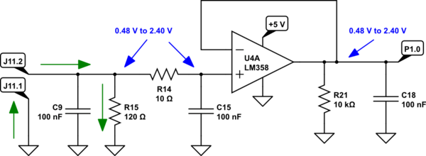
op amp - How does this circuit read 4-20mA current loop input through

APD Bias Circuit Has Adjustable Output - Maxim Integrated