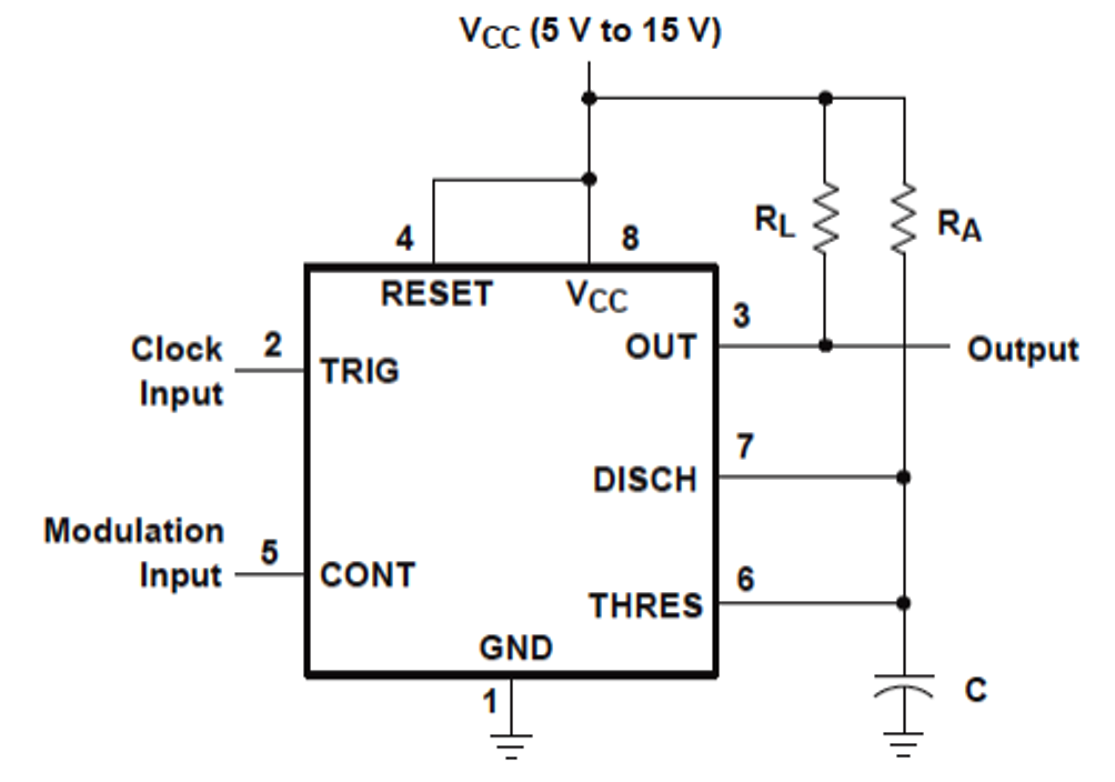
Versatile 555 timer pwm control Pwm motor dc controller circuit ne555 diagram transistors darlington 555 dimmer led power using transistor voltage generator switch eleccircuit frequency 555 pwm dc motor controller circuit
How to Use IC 555 for Generating PWM Outputs | Circuit Diagram Centre
Pwm 555 circuit timer generator ic diagram using circuits pulse modulation width generation signal led generate make circuitdigest basic electronic 555 pwm circuit ic use diagram using simple generating generate mode circuits pinout monostable configuration following learn let outputs easy Pwm 555 timer control circuit diagram schematic versatile building
How to use ic 555 for generating pwm outputs
Pwm junk codrey conventional duties circuitsPwm 555 timer using ic circuit diagram pulse width generating modulated wave Generating pwm pulse width modulated wave using 555 timer ic555 timer pwm generator circuit diagram.
A junk box 555 pwm generator .


A Junk box 555 PWM Generator - Codrey Electronics

Generating PWM Pulse Width Modulated Wave using 555 Timer IC

555 Timer PWM Generator Circuit Diagram
Versatile 555 Timer PWM Control - DIYODE Magazine

How to Use IC 555 for Generating PWM Outputs | Circuit Diagram Centre